|
||||
|
||||
|
||||||||||
Jonas Romblad works as a "windtunnel engineer" doing aerodynamic research.
His new 50-öres (F1M) model flies just as slow as
old F1D's. I am really impressed by his performance!
Over to Jonas and his story:
During the autumn of 1995 I did some experiments regarding the wings of indoor models. The results were applied to a F1D-beginner class model to be discussed later.
First, let's rephrase the question slightly. On a mini-stick, EZB or F1D, we all know the covering, curved to an arch, is actually making up the major part of the airfoil. The question could therefor be; where, with respect to the covering should the ribs and especially the spars be placed?
To answer this question some tests were performed using a small balsa wood glider. The glider had a sheet balsa wing curved to an arch, camber being 4-5% of the cord. The wing had a cord close to 1/3 the cord of the F1D-beginner I was designing and flew about 3 times as fast. This meant the glider and the F1D-beginner operated at the same Reynolds number - something quite important for this kind of test. The glider was flown from a catapult which would launch it at the proper glide angle and airspeed. Naturally all testing was done indoors to eliminate wind interference.
To simulate the leading and trailing edge spars, several layers of adhesive tape were laminated to the scale (1/3) height of the real spars and cut to the scale width. These "spars" could then be placed on top or bottom of the sheet balsa wing to simulate the real spars being put above or below the covering.
The flight times were too short to measure performance directly, but the flight behavior of the model was studied. The model was flown both in symmetric and asymmetric configurations, for instance leading edge on top of the right wing but below the left.
Using the normal ( both spars under the covering) as a reference the
following observations were made:
Symmetrically placed "spars".
1. LE spar above and TE spar above covering: Slight dive. CG moved aft
to trim.
2. LE spar below and TE spar above covering: More steep dive. CG moved
further aft to trim.
3. LE spar above and TE spar below covering: Nose up or stall. CG moved
forward to trim.
Asymmetrically placed "spars" induced rolling and yawing. If the left
wing was left in the reference configuration (both spars under the
covering) the following observations were made:
1. LE spar above and TE spar above covering: right turn.
2. LE spar below and TE spar above covering: right turn. Tighter than in 1.
3. LE spar above and TE spar below covering: left turn. Less tight than
with configurations 1 and 2.
My conclusion was that the wing with the leading edge above and trailing
edge below the covering generated more lift than the other
configurations.
However, there are possible pitfalls. As the leading edge is moved to
the top of the covering, the point of stagnation is possibly moved
upward too. This would mean that the effective angle of attack is
increased with increased lift as a result; something which does not mean
any increased performance. Also, the method is too coarse to clearly
detect any changes in drag.
So, what caused the apparent change in glider behavior?
The positive effects of having a small "lip" hanging down under the
trailing edge of an airfoil has been known for long. Such a device,
called "Gurney Flap", will generally increase maximum lift at a small
increase in drag. The TE spar acts as a Gurney flap increasing lift, as
indicated by the experiments.
What happens around the leading edge spar is more complicated and strongly coupled with the low Reynolds number our models are operating at. My theory is that the leading edge placed on the wing upper surface acts as a turbulator, trigging or at least helping a transition to a turbulent boundary layer. The turbulent boundary layer is less prone to separating and an early transition may therefor reduce the drag and increase lift.
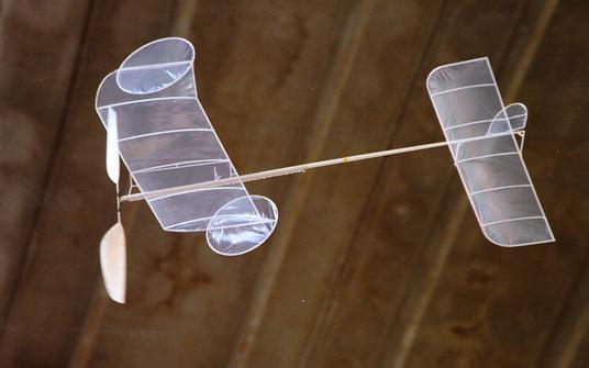
As mentioned earlier, I built a F1D-beginner model using the results from these tests. The wing has the leading edge on top of the covering and the trailing edge on the bottom. For practical purposes, the ribs were placed above the covering. As the ribs represent a very small part of the wetted surface I doubt the increase in drag due to the higher velocities on the upper surface will have any but a neglectable effect. Putting the ribs on top also makes the covering easy, maybe even easier than covering the normal way. Also, the air loads will push the covering against the ribs so the covering can be spot-glued to the rib every inch or so reducing weight slightly (perhaps not enough to matter).
Although far from a comparative test, the model flies quite well at a very low speed. Flight speed at cruise has been clocked at 0.8 m/s. It has been flown at two competitions, the 1995 Swedish nationals and a local competition this spring, taking first place both times.
Jonas Romblad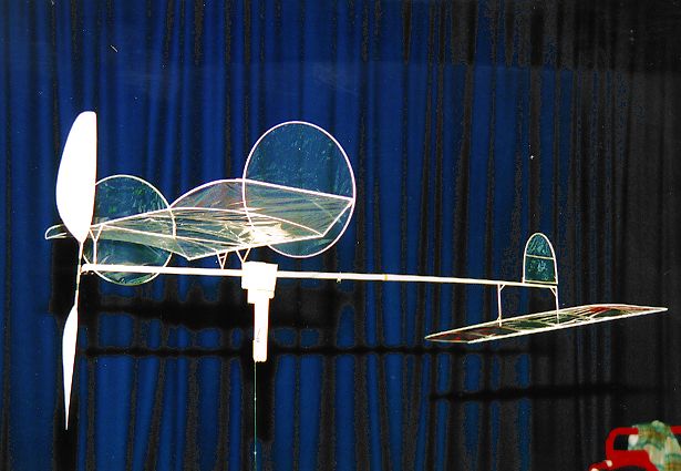
|
|||||||